
I have been hard at work on the bavacade this weekend going through part 1 of the to-do list. I would like to make each game’s repairs a post of its own, but if I don’t capture this stuff in the moment I forget it pretty quickly, so going to try and quickly record some of the repairs over the last few days and then use these logs as notes for longer posts, or at least that is the plan.
Venture
I knew a good part of this weekend would be dedicated to Venture, and I wasn’t wrong. I spent much of yesterday afternoon testing the K4600 from Galaxian (which worked!) and then methodically testing all voltages and continuity on the edge connector from the power supplies.

Color bar test on Venture for WG Test Pattern Generator is a success
I’ll start with the win: the Wells Gardner K4600 monitor chassis from Galaxian worked in Venture. At first the screen was black, but after connecting a Wells Gardner Test Pattern generator I picked up last year I was able to confirm the chassis is fine, and that the original K4600 I had in there needs a capkit, or more given it was completely dead. Here is a quick video of the test pattern generator tool, which is pretty cool:
After that, I started methodically testing all the voltages from the universal power supply to both the audio board and main logic board edge connectors. The universal power supply delivers +12V (hi), +12V (lo), -12V (hi), -12V (lo), and -5V.* I was testing for continuity to begin with, and then switched to testing for voltages but got confused and linked a 12V charge with a non-charged connector and a resistor on the main logic board started smoking. It was a rookie mistake, and I’m not happy. That said, I’m hopeful I didn’t fry the entire logic board given there were no additional signs of damage after a close visual inspection, but that might just be wishful thinking.

Resistor 302 is fried, let’s hope that’s all that fried
I’m waiting to get a packet of resistors to change the one I fried out and then test the board again. While doing the close inspection of the board I realized the edge connectors might have been inverted, which would make some sense given the audio board seemed to be getting no power at all. That would be a very bonehead mistake on my part, but I was sure I checked that when the game was still in America and I was troubleshooting there, if that is the issue then we may have a working Venture soon (assuming it is not fried).
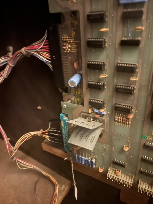
Venture‘s Main logic board and audio/video board edge connectors
I printed out a copy of the wiring diagram for Venture, and used it to record the values, and this was helpful. It’s pretty cool that I am starting to wrap my head around these things that were traditionally unintelligible to me.
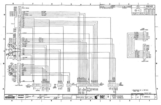
Venture wiring diagram with annotations
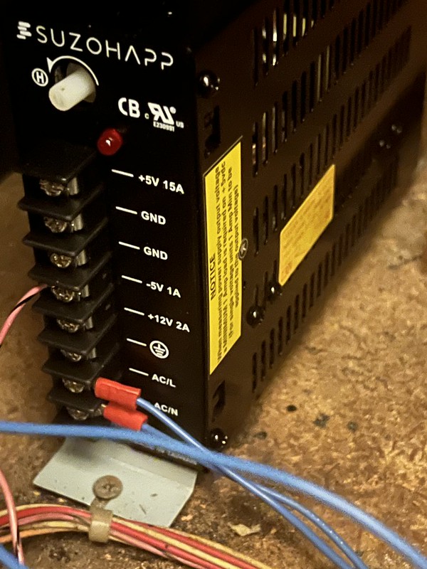
The other thing to note on Venture is that I am pulling in only the -5V from a switching power supply given it is not working on the original universal power supply. The +5V is working on the original power supply, in fact it is high at +5.4V, but that is generated separately from the +/-12Vs and -5V on this particular power supply. When I tested the -5V from the switching power supply to the edge connector while grounding to the universal power supply I got no reading. But when I grounded it to the switching power supply I could see the -5V successfully delivered. I’m wondering if this might be causing a problem for delivering -5V to the audio and main logic board. I’m not entirely sure—but I’m thinking about piggybacking the ground from the switching power supply to the universal power supply ground for -5V just to be sure. I’ll consult with an expert or two before I do given I’m at the edge of my already limited understanding of electrical systems and I don’t want to cause any more unnecessary damage.
Left to do on Venture is repair the burnt resistor, ground -5V to universal power supply (maybe), and invert edge connectors after testing the rest of the values given I think a couple/few +5V readings are outputs from the main logic board to the control panel, audio/video color board, and coin door that depend on being mediated through the main logic board, so I don’t think the absence of +5V reading on those connectors is accurate, but we’ll see.
Dig Dug and Bagman

Dig Dug is looking good after swapping in the G07 I did a capkit on, proud bava!
So while Venture was a mixed bag at best, swapping G07 chassis between Bagman and Dig Dug was a win. and particularly sweet win because it is a G07 chassis I did a capkit on that I thought was having issues in Bagman, but was not in Dig Dug and it solved the jerkiness problem. In fact, both Bagman and Dig Dug no longer have monitor issues, and I can relish my first truly successful capkit, the success of which buoying me to try one on the K4600 from Venture that’s dead, maybe later this week.

Dig Dug looking good!
Anyway, this means the only things left on Dig Dug are to get the marquee and coin door lights working and eventually a bit of cabinet repair on the lower back portion of the base. Will hopefully have Alberto work on that later this fall.
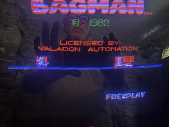
Sprite issue on moving elements of Bagman
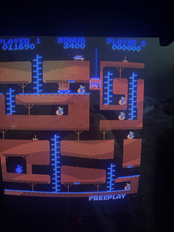
Sprite issue on moving elements of Bagman
As for Bagman, that is already entirely minted out, the only remaining issue is after the board heats up the moving sprites start to pixelate and loose all definition into a striated color blob, so this is another board to ship along side the Cheyenne, and Moon Patrol.
Asterock
I had big plans for removing the switching power supply from Asterock in order to consolidate that cabinet down to one wall plug and have everything running off the original power supply that has been repaired, including the heat sync Roberto fixed.

Heat sync installed
But after looking at all the various wires I would have to move from the switching power supply to the edge connector I got scared.
Switching power supply inputs from edge connector on Asterock
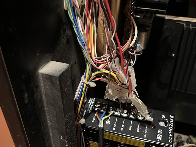
Instead, I opted to simply hook power for the switching power supply (which was using its own wall plug) into the AC power lines using a few piggyback connectors that look like the following:

Piggyback connector for tapping into 120V for switching power supply
Here is what the piggyback connectors look like in action, the brown and blue wires from the switching power supply are tapping into the main AC power lines (also blue and brown) going into the original power supply, and the green/yellow wire is the ground that is screwed onto the power supply along with several other grounds wires.

Brown and blue wires are 120V AC and green/yellow is ground, the close-up above shows the connections coming into the switching power supply
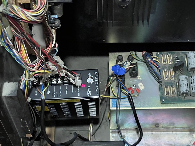
Overview of tapping 120V AC for switching power supply from AC wires coming into original power supply from the wall

Close-up of piggyback connectors tapping into AC going into original power supply
If I was an absolute purist I would have removed the switching power supply, but given this game already had power issues I think using the switching power supply will preserve the original that much more 🙂 Anyway, my plans to consolidate to one wall plug worked and Asterock is still running in all its vector glory. Asteroids was truly one of the most gorgeous video games ever made.

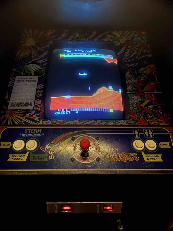
Super Cobra and Defender
On a smaller note, I added back door locks to Defender and Super Cobra, and I will add another to Bagman, replace both on Yie-Ar Kung-fu, and another to the back of Galaxian. I think after that I might need a few more, but we’ll see.
____________________________________________________
*I’m not exactly sure of the distinction between high and lo here, but I think it suggests +12V tends towards more than the expected 12V, and 12V low means a bit less, like 11.90 or so, but I am not sure. That was wrong, I researched this and Ken Layton (RIP!) lays it out as clearly as he always does on the Arcade Forums:
The hi/lo means this:
+12v HI = +12 volts @ 3 amps
+12v LO = +12 volts @ 1 amp
-12v HI = -12 volts @ 3 amps
-12v LO = -12 volts @ 1 amp
In essecence you have two seperate +12 volt power supplies: one that can output a peak of 3 amperes and another that can output a peak of 1 ampere. Same goes for the -12 supply.
So what it boils down to is that are “electrically” four seperate 12 volt power supplies in there. I don’t think you’re going to find any power supplies made today that can put out a minimum of 4 amperes on the -12 volt line.

Pingback: bavacade To-Do List, Part 2 | bavatuesdays